Vibration Assessments
Picture the scene. Just two days after delivery to its owner, a new ship has to be taken back into dry-dock. The reason? Vibration levels so severe that they have caused fatigue cracks in the hull, causing water to enter internal compartments. Dry-docking is the only option to solve the problem.
Another example: A 10-year-old general cargo vessel completes its latest voyage. The crew breathe a collective sigh of relief as they enter port for this means that the engine RPM drops to a level that does not result in bone-shaking vibrations in their cabins and living quarters.
These two examples demonstrate that vibrations on ships can have multiple consequences. Affecting both new-build vessels and ‘working’ vessels alike, vibrations can cause structural damage and electrical component failure, both of which lead to costly downtime and unexpected repair costs. It can also result in a crew that is tired and frustrated, leading to potential safety and welfare issues.
Source – path – receiver
C-Job’s work on vibration assessments aims to prevent resonance in an efficient way. Expert Structural Engineer and R&D Consultant Rolph Hijdra is coordinating this work. In explaining the subject, he is keen to define some of the terminology and processes involved.
“There are three important aspects to identify when talking about vibrations on a ship. First, there is the source of vibration. This can be the propeller or propeller shaft, propeller blades, the engine or any other dynamic piece of machinery. Even the water currents causing vortices around submerged hull structures. Then there is the path of vibration from the source to the receiver. The receiver is where the effect of the vibration is observed. This can be a person, or it can be a structure, for example, the deckhouse. Or it can be electronic equipment, at the top of a mast, for example.”
Mirroring these three aspects, there are three principal means to reduce vibrations on an existing vessel. Number one: modify the source. “Solutions include changing the number of propeller blades, changing the number of cylinders in the engine. Or remove the source completely; reshape submerged hull structures such that vortices do not appear anymore, for example,” says Rolph. Number two: modify the path. “This involves doing something to stop the transmission of the vibration from the source to the receiver. This mainly involves using insulation.” Number three: modify the receiver. “Vibrations are related to mass and stiffness, so possible solutions include strengthening constructions, and adding or removing mass. You can use damping when vibrations are unavoidable; rubber engine mounts are a great example of damping.”
An integrated approach
Although C-Job can indeed help solve vibration issues on existing vessels, the company intends to prevent vibrations from occurring in the first place that are most impressive. By addressing the subject of vibrations during the ship design phase, the problem is solved before it even exists.
“This is what we are aiming for,” Rolph notes. “We want to avoid excessive vibration levels; resonance at any point is not allowed.” Furthermore, thanks to how C-Job incorporates this into their projects the whole design process is made more efficient. Using the process of designing stiffened plate panels to illustrate his point, Rolph shows the diagram below. “This is the common approach for the process of creating a basic design. You see that the vibration calculations are at step 6, after the design has been sent for class approval.”
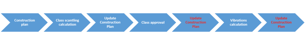
“We shift the vibration assessment to a point in time where we are carrying out the scantling calculations. This reduces the time involved for all the calculations, only having to update the construction plan once before and once after class approval. The flow diagram below shows the reduction of lead-time and overall time of basic design. What’s more, this creates a more optimized structure, resulting in less vessel weight.”

Substructures
Vibration assessments for complex substructures and complete hull structures require a different method. This is where C-Job’s finite element analysis capabilities comes into play. Rather than building common time-consuming finite element models, the company has devised a new method.
“This method gives us the option to reuse our 3D structural model which we create in NAPA steel,” Rolph explains. “We can reuse it within our finite element software ANSYS, where we can perform the natural frequency analysis. This link between the structural model and finite element model gives us the advantage in lead-time, total time, and quality of work.”
The finite element model also allows C-Job to work on all the different mode shapes of a structure; it is not limited to plate panels. “We can analyze any structure or substructure. Mast, deckhouse, helicopter platform, whatever is required.”
Is vibration assessment unique to C-Job?
In answering the above question, Rolph’s response is open and honest. “This type of analysis is not unique – there are more companies that can do this. It isn’t rocket science.” However, by incorporating this into the overall process at an earlier stage, C-Job delivers serious added value to its clients on the subject of vibrations. “The way that we implement these techniques – by combining it in the early stage of design and including the finite element analysis and integrating the structural model – this is important. This generates a streamlined process. The one-stop-shop as I call it.”
The science of vibration in a nutshell
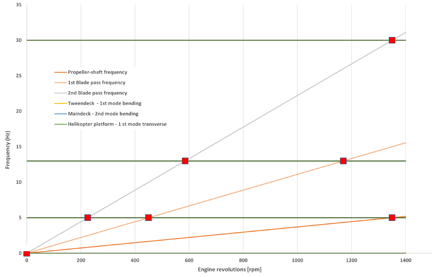
Even though Rolph Hijdra has stated above that “this is not rocket science”, the graph below indicates just how challenging the process of vibration assessment can be. This is a Campbell diagram, giving an overview of vibrations occurring in a given system.
Here, vibration is classified as resonance; this is dynamic amplified motion. If the excitation frequency is equal to the natural frequency (which corresponds to the stiffness and mass of the construction) then resonance occurs. To make things more complex, each system has multiple natural frequencies
Campbell diagram
The horizontal lines represent the natural frequencies of multiple mode shapes of the ship. This includes the hull and various substructures. The sloped lines represent all the sources of vibration within a ship. Everywhere where a horizontal line crosses a sloped line, there is risk of resonance. The Campbell diagram shows just how many potential sources of resonance (vibration), and how many natural frequencies, there are on a ship. This might not be rocket science, but it is certainly very specialist work.